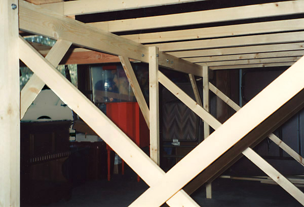
The bench work base consists of L beams made of 1x3 capped with 1x2 that are glued and secured with screws at 1 foot intervals. The stringers across the tops of the beams are 5 foot 1x2's spaced 1 foot apart and secured by screwing up through the 1x2 portion of the L beam. Over the 15+ years since the layout was initially constructed, there has be no visible sign of sagging or warp of the base grid members.
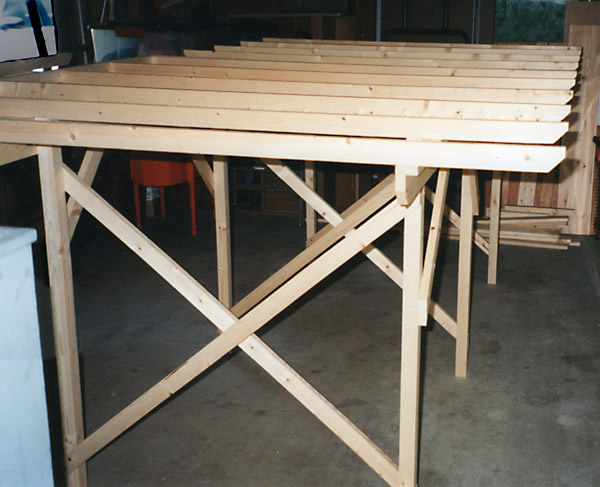
The legs are 2x2 cut for a 42 inch height of the grid base with 1x2 diagonals. All leg diagonals are glued and screwed for extra rigidity. The completed approximately 125 pound layout is stand alone and rock solid; no sway tendency at all. Leveling feet, not pictured, were added to the bottoms of the legs.
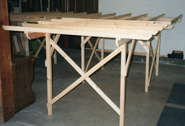
A single 1/4 inch carriage bolt secures the legs to the L beams. The base was constructed as a 5 by 5 foot and two 5 by 4 foot sections that are joined with splices. Helps to simplify disassembly for movement should that ever be necessary.
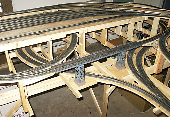
Industrial spurs in center, yard approach track and soon to be hidden portion of level 2 track.
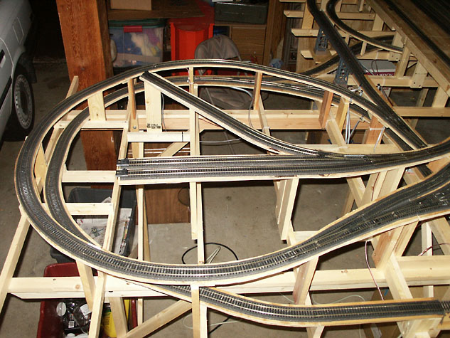
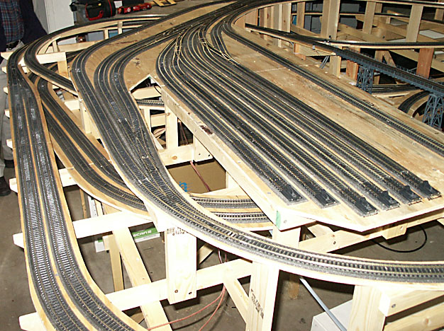
Yard, level 3, level 2, and level 1 holdover tracks.
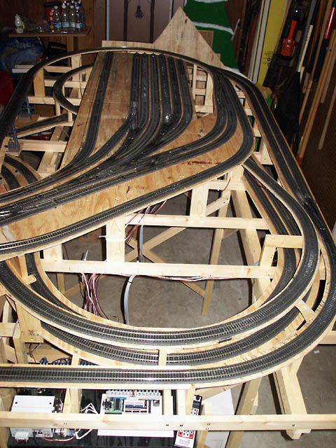
Level 4 wye turnout just visible. Yard approach track bridge and entrance to the soon to be hidden level 1 holdover tracks.