10-27-2018: Motherboard connector layout planning.
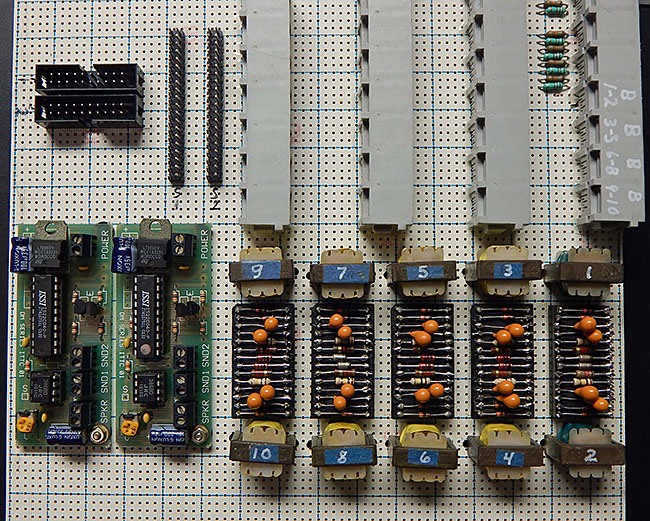
2-02-2019: Block detector circuits wired and tested. Point-to-point soldered connections using 30 AWG wire wrapping wire. Placing a 1K resistor across the rails yields about 4.1 volt signal level at PP1 Bus1 connector.
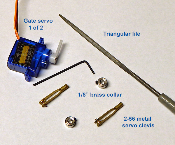
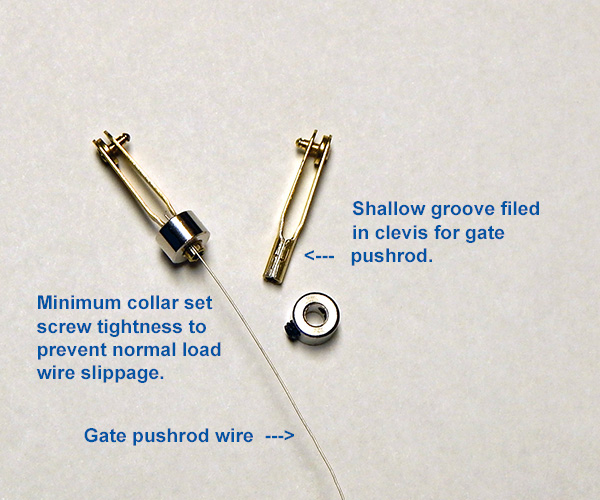
5-09-2019: Crossing gate to servo mechanical connection.
A servo clevis is attached to the existing gate pushrod wires using a 1/8 inch collar. The clevis is also 1/8 inch at its base so a shallow grove must be filed in the clevis to allow the collar and wire to slip on. This design simplifies gate position adjustments once the servos are mounted.
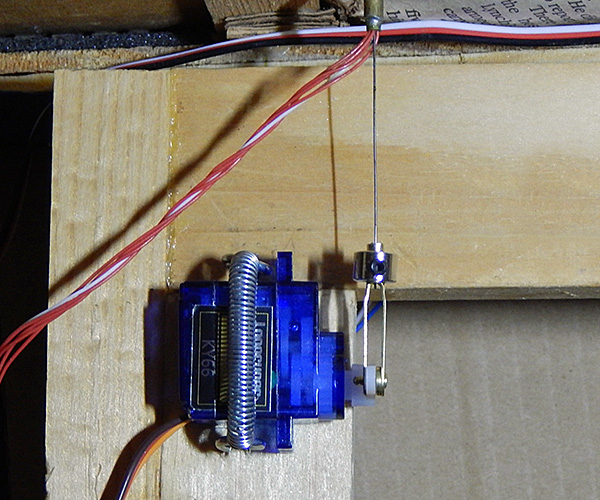
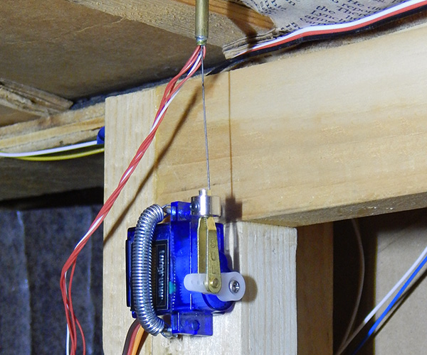
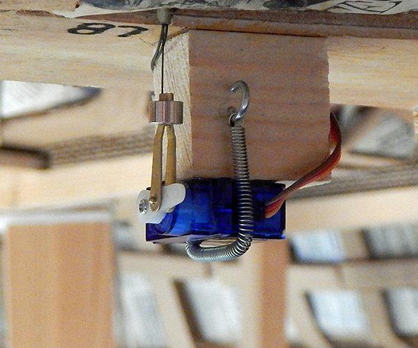
Despite their small size, the servos are powerful enough to possibly cause gate damage if erroneously positioned. In addition to not over tightening the collar set screws, the servos should be loosely mounted to the layout frame allowing them to twist if a gate mechanical limit is encountered. This is easily accomplished by using small hooks and a metal spring. If the servo shifts position during normal operation, glue a small piece of 100 or 120 grit sandpaper where the layout frame contacts the servo.
Grade crossing gate servo mechanical adjustment procedure. If the servo has been disconnected from the gate pushrod, begin at step 1. Otherwise, begin at step 8. 1. Verify clevis attachment to inner hole of servo arm. Clevis should move freely but have a snug fit. Lubricate if needed using dry graphite (door lock lubricant). 2. Join the gate pushrod, collar, and servo clevis. Leave collar setscrew loose so pushrod wire can easily slide. 3. Disconnect the 3 pin servo cable from the external board. 4. Edit TurnoutDataFile.txt. Set Open, Middle, and Close values for the gate servo to 595, 600, and 605 respectively. 5. In RPi console, enter DnB.pl -m x (x is servo number) to set gate servo to the middle position. 6. Connect the 3 pin servo cable to the external board. The servo will move to the middle position. 7. Manually move the signal gate to mid position. Then tighten the collar setscrew to attach the gate pushrod to the servo clevis. 8. Enter DnB.pl -c x console command to set gate servo to the Close position. 9. Note gate position and change value in TurnoutDataFile.txt in small increments to achieve desired gate lowered position. 10. Enter DnB.pl -o x console command to set gate servo to the Open position. 11. Note gate position and change value in TurnoutDataFile.txt in small increments to achieve desired gate raised position. 12. Repeat for the second gate servo. 13. In RPi console, enter DnB.pl -g2 to run test and verify desired gate operation. Some dry graphite lubrication inside the pushrod guide tube will help smooth out the movement. 14. Edit TurnoutDataFile.txt. For the gate servos, set the MinPos and MaxPos values to the appropriate Open and Close value. This will help prevent erroneous servo positioning beyond a physical limit which could possibly damage the gates.
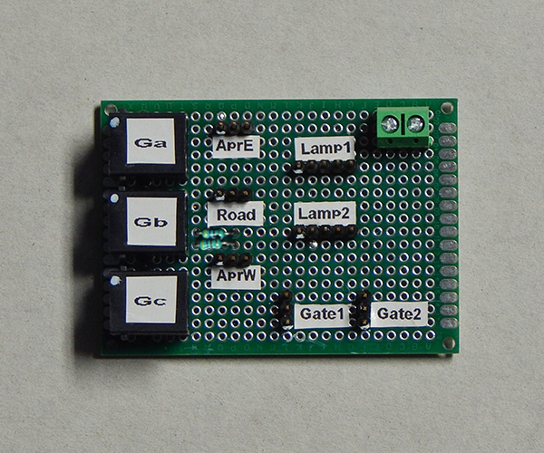
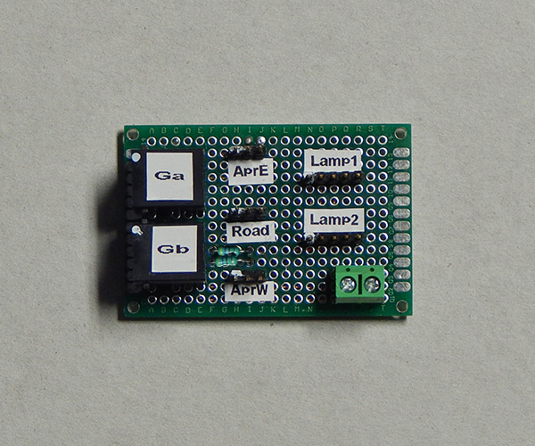
Off the shelf (Amazon) wiring boards that are mounted external to the main board at grade crossing locations. Combines connections for signal LEDs, IR sensors, speaker, and gate servos.
Grade crossing signal lamp connection procedure. 1. Attach a female pin connector to each (5) grade crossing signal LED wire. 2. Ensure proper attachment of external board to mainboard via 6 pin cables. 3. In RPi console, enter DnB.pl -g1 to run grade crossing test. 4. Connect signal LED common to external board lamp header pin 1. 5. Attach LED wire to pin 2 of lamp header. Note flashing lamp. 6. Attach in turn the remaining LED wires to the lamp pin header to achieve desired alternating lamp pattern. 7. Repeat steps 4 through 6 for second signal. Grade crossing operation YouTube clips: Grade Crossing 1 Grade Crossing 2
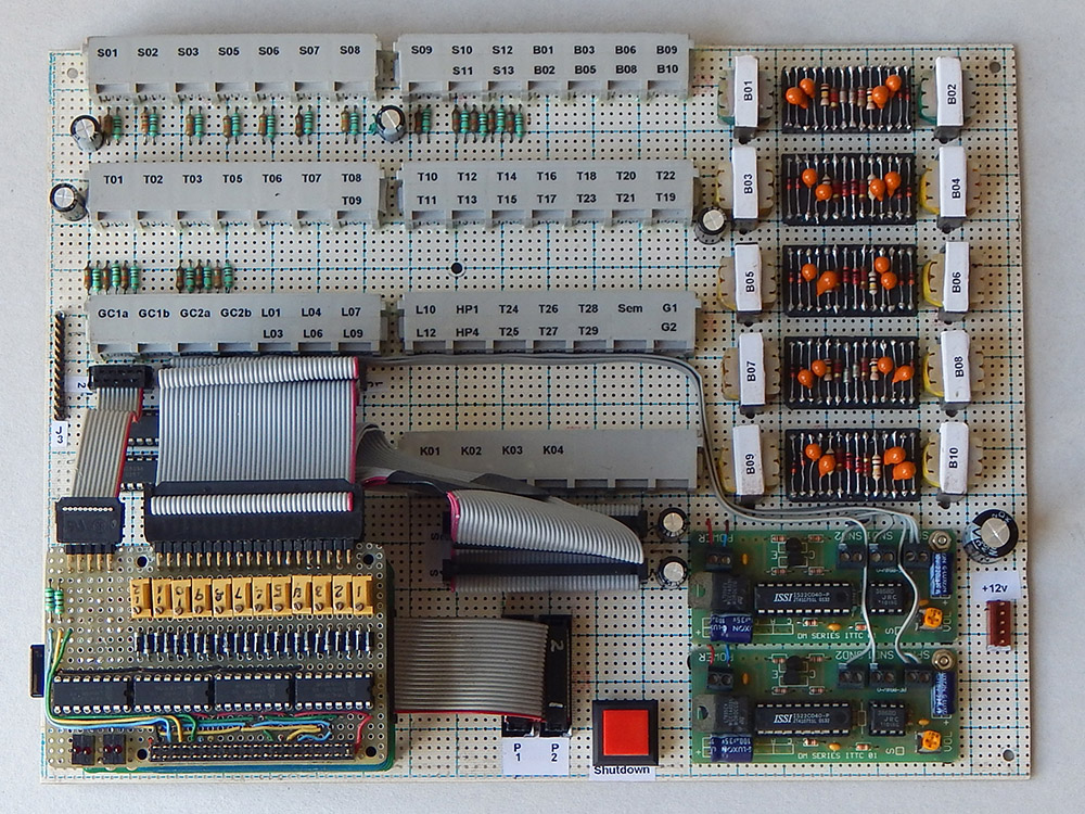
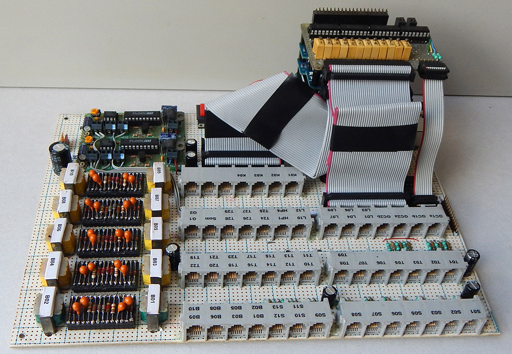
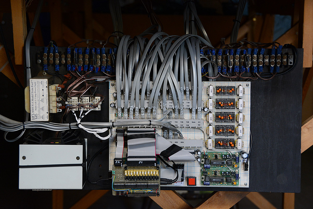
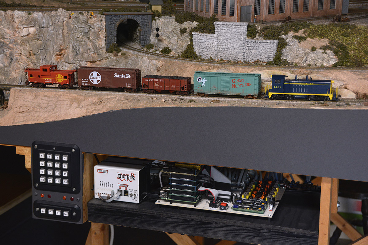
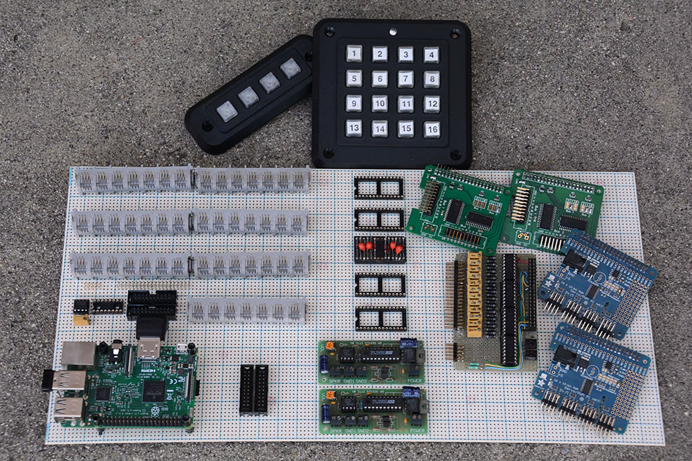
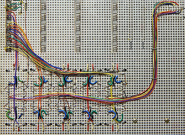
5-20-2019: Mainboard with all wiring and components.
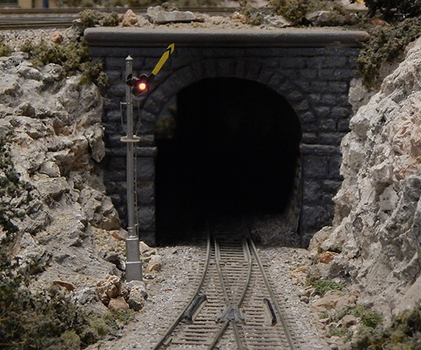
6-01-2019: Semaphore to servo mechanical connection.
In a manner similar to the grade crossing gates, a clevis is used to attach the semaphore flag pushrod wire to the servo.
Semaphore flag board servo mechanical adjustment procedure. If the servo has been disconnected from the pushrod, begin at step 1. Otherwise, begin at step 8. 1. Verify clevis attachment to inner hole of servo arm. Clevis should move freely but have a snug fit. Lubricate if needed using dry graphite (door lock lubricant). 2. Join the pushrod, collar, and servo clevis. Leave collar setscrew loose so pushrod wire can easily slide. 3. Disconnect the 3 pin servo cable from the external board. 4. Edit TurnoutDataFile.txt. For the semaphore servo, set the Open, Middle, and Close values to 595, 600, and 605 respectively. 5. In RPi console, enter DnB.pl -m x (x is servo number) to set the semaphore servo to its middle position. 6. Connect the 3 pin servo cable to the external board. The servo will move to the middle position. 7. Manually move semaphore flag board to yellow (mid) position. Then tighten the collar setscrew to attach the pushrod to the servo clevis. 8. Enter DnB.pl -c x console command to set semaphore servo to the Close (Red) position. 9. Note flag board position and change value in TurnoutDataFile.txt in small increments to achieve desired red position. 10. Enter DnB.pl -o x console command to set semaphore servo to the Open (Green) position. 11. Note flag board position and change value in TurnoutDataFile.txt in small increments to achieve desired green position. 12. In RPi console, enter DnB.pl -s x (x is signal number) to run test and verify semaphore operation. The semaphore can be positioned to each color using 'DnB.pl -s Grn:x', 'DnB.pl -s Yel:x', 'DnB.pl -s Red:x', or 'DnB.pl -s Off:x' 13. Edit TurnoutDataFile.txt. For the semaphore servo, set the MinPos and MaxPos values to the appropriate Open and Close value. This will help prevent erroneous servo positioning beyond a physical limit which could possibly damage the semaphore. Semaphore operation YouTube clip: Semaphore clip
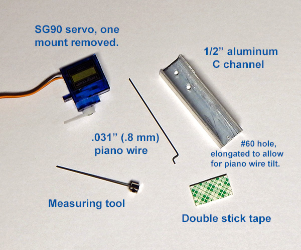
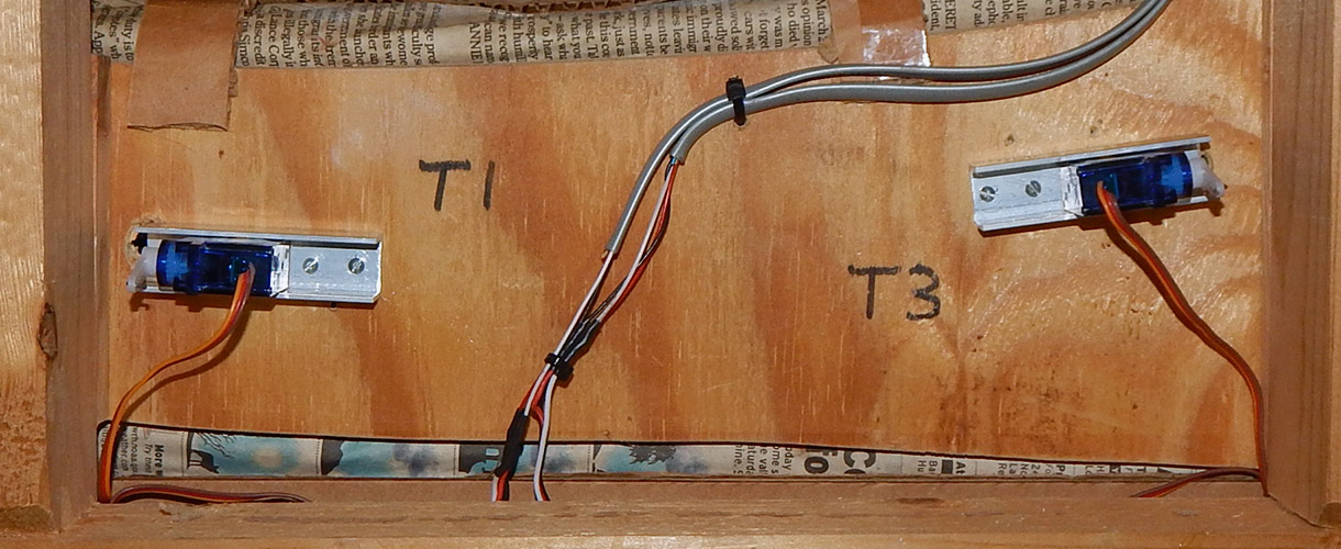
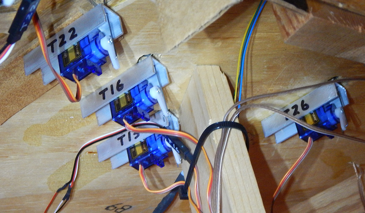
6-03-2019: Turnout to servo mechanical connection.
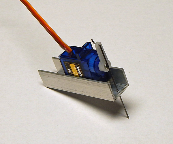
A piece of 1/2 inch aluminum C channel, about 2 1/4 inches long, is used to attach the SG90 servo to the underside of the track board. Holes slightly larger than the mounting screws are drilled to permit some lateral positioning of the C channel. A hole is drilled near the opposite end of the C channel to permit passage of the piano wire actuating rod, #60 for .031 inch (.8 mm) piano wire. The #60 hole must be elongated slightly to permit free wire tilt when moved left/right by the servo. The servo mounting tab is removed flush with the servo case allowing a piece of Scotch Permanent Mounting square (111-LRG) to hold the servo in place.
A measuring tool was devised to assist with C channel placement, determination of actuating rod length, and location of the Z bend. With the points roughly centered between the rails, the measuring tool wire is passed down through the hole in the turnout throw bar and temporarily secured with tape. The C channel/servo is then held in place with the tool wire passing through the #60 hole. Once satisfactorily squared up, marks through the C channel mounting holes can be made on the underside of the track board for mounting screw pilot holes. A small mark is also made on the tool wire for the Z bend location. The tool wire is then used to measure, cut, and bend a piece of piano wire into the actuating rod for the turnout location.
Turnout servo mechanical adjustment procedure. 1. Ensure servo/C channel is mounted snug (not tight) to track board. This allows for some twist positioning of the turnout middle position. 2. Temporarily remove the servo horn from the servo drive shaft. 3. Edit TurnoutDataFile.txt. For the turnout servo, set Open, Middle, and Close values to 550, 600, and 650 respectively. 4. In RPi console, enter DnB.pl -m x (x is servo number) to set the turnout servo to its middle position. 5. Connect the 3 pin servo cable to the main board. The servo will move to the middle position. 6. Press the servo horn onto the servo drive shaft as shown in the image. That is, pointing away from the track board. If the spline prevents optimal horn placement, change Middle value by 10 (step 3) and re-enter command (step 4). Repeat as necessary. Servo horn securing screw will be re-attached later. 7. Twist C channel if necessary to approximately center the points between the outer rails. Then tighten C channel mounting screws. 8. If the Middle value was changed in step 6, edit the TurnoutDataFile.txt and change the Open/Close values to +/- 50 steps from the new Middle position value. 9. Enter DnB.pl -c x console command to set the turnout servo to the Close position. 10. Note turnout point position and change the turnout's Close value (step 3) by a small amount until the proper turnout point lightly touches the fixed rail. Perform step 9 after each value change. It may be necessary to swap the turnout Open/Close values in TurnoutDataFile.txt to achieve proper direction of motion. 11. Enter DnB.pl -o x console command to set the turnout servo to the Open position. 12. Note turnout point position and change the turnout Open value in TurnoutDataFile.txt by a small amount until the proper turnout point lightly touches the fixed rail. Perform step 11 after each value change. 13. In RPi console, enter DnB.pl -t x (x is turnout number) to run test and verify turnout operation. The turnout can also be positioned using 'DnB.pl -t open:x', 'DnB.pl -t middle:x', or 'DnB.pl -t close:x' 14. With the servo in the Middle position, disconnect the 3 pin servo cable. Carefully re-attach servo horn securing screw. Then reconnect the 3 pin servo cable. 15. Edit TurnoutDataFile.txt. For the turnout servo, set the MinPos and MaxPos values to the appropriate Open and Close values. This will help prevent erroneous servo positioning beyond a physical limit which could possibly damage the turnout. 16. Once the turnout is operating properly, the turnout values in TurnoutDataFile.txt should be entered into the %TurnoutData hash of your DnB.pl file. This ensures that the proper turnout position values will be regenerated if the DnB.pl -f option is used. Turnout operation YouTube clips: Turnout T08 Turnouts T01 and T03
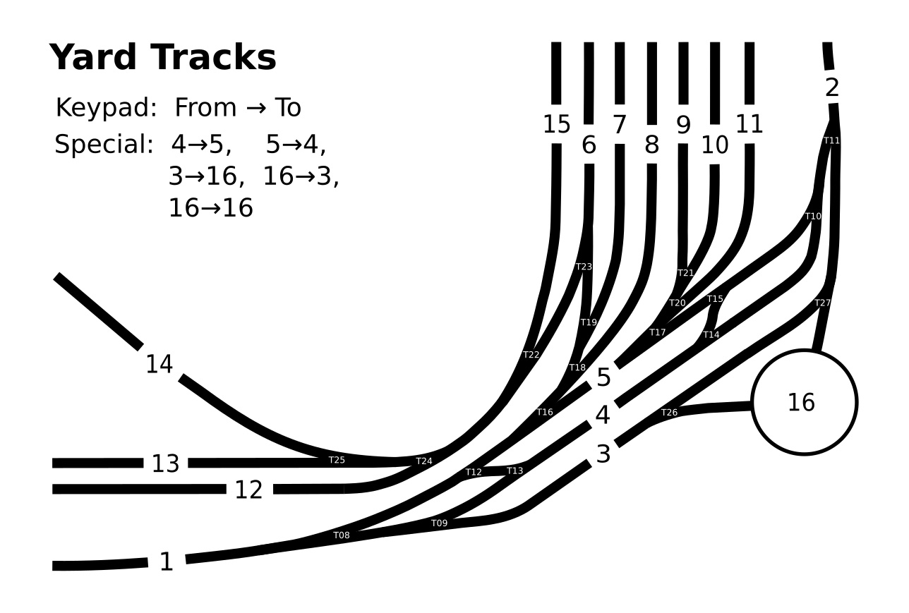
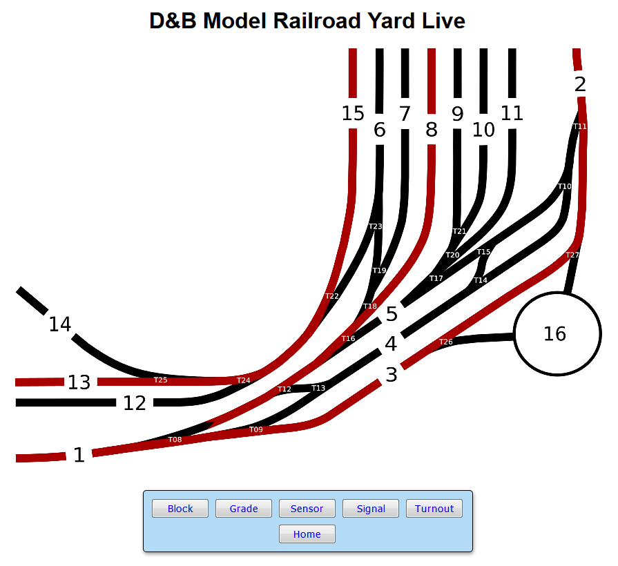
6-18-2019: Conversion of Atlas undertable switch machine to servo drive, including associated wiring changes, is complete. All turnout servos are mechanically mounted and their associated open/close position values set for proper turnout point positions. Turnouts are operational using test code. Yard trackage diagram created with open source Inkscape Draw Freely program.
6-19-2019: RPi mainboard and associated layout wiring complete. Time to start debugging the operational code.
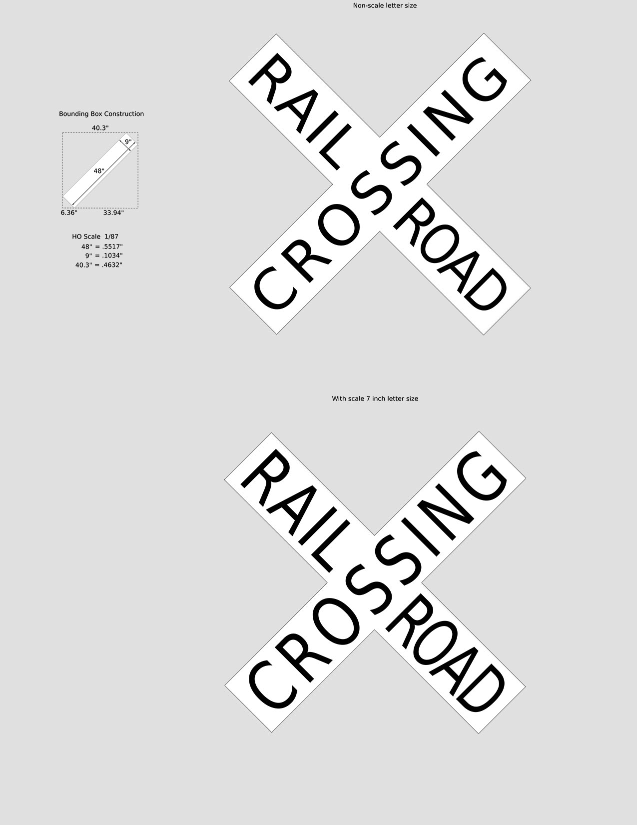
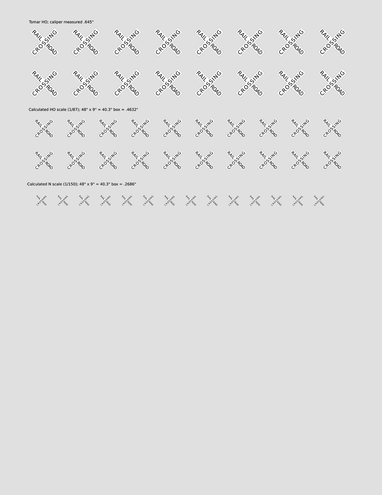
7-23-2019: Needed to replace the crossbuck decal on one of the Tomar grade crossing signals. Unable to find suitable decals so the Inkscape Draw Freely program was used to create some. Inkscape SVG and 600 dpi PNG files are here: rpi-crossbuck.zip. An inkjet printer, Testors decal paper (white) and Testors fixative will be used. The grey background in the images is for visualization. The source files have a transparent background.
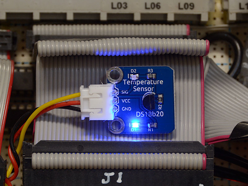
8-08-2020: To help compensate for layout benchwork thermal expansion/contraction that affects gate and semaphore positioning, an ambient temperature sensor made by SunFounder, the DS18B20 Temperature Sensor, was added to the control electronics. The sensor cable is electrically attached to the RPi 40 pin connector on the 74HC595 shift register board pins 2 (5v), 6 (Gnd), and 7 (GPIO4). The sensor board is loosely located in the J1 ribbon cable fold.
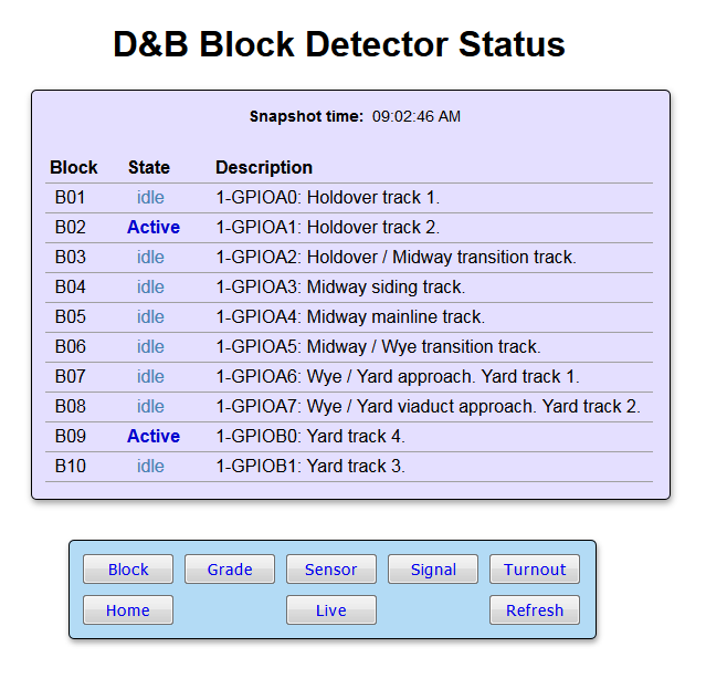
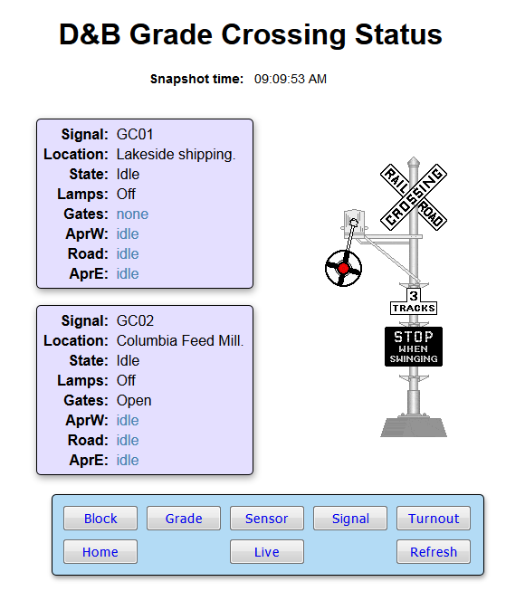
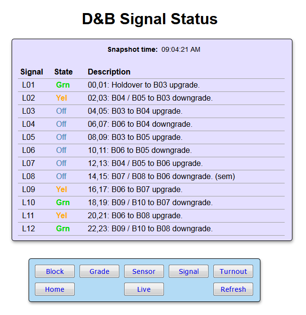
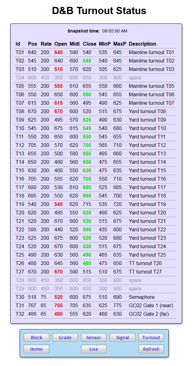
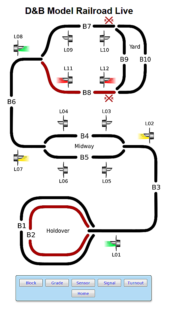
9-15-2020: Some screen captures of the web browser based read-only interface. The locomotive and wig-wag crossing signal are animated GIF images. Perl code dynamically creates the HTML for the tables based on current layout operational values. The Live page uses a background track plan image that is overlayed by transparent images. Each overlay colors its associated track block/signal based on current layout operational values.
10-13-2020: Screen capture of web browser Yard Live web page. The current turnout lined track routes are shown in red.